 English
 Spanish
 French
 German
 Italian
 Chinese (Simplified)
 Japanese
 Korean
 Arabic
 Portuguese

Four Probe Set Up FP-01N/ FP-01C
Product Details:
- Application Laboratory Experiment
- Weight 25 Kg Kilograms (kg)
- Material Electronics
- Color Grey
- Usage Laboratory Experiment
- Display Type Digital
- Click to View more
Four Probe Set Up FP-01N/ FP-01C Price And Quantity
- 1 Set
Four Probe Set Up FP-01N/ FP-01C Product Specifications
- Laboratory Experiment
- Digital
- 25 Kg Kilograms (kg)
- Laboratory Experiment
- Electronics
- Grey
Four Probe Set Up FP-01N/ FP-01C Trade Information
- Cash Against Delivery (CAD), Cash on Delivery (COD), Cash Advance (CA), Cash in Advance (CID), Cheque, Delivery Point (DP), Telegraphic Transfer (T/T)
- 100 Set Per Month
- 1 Week
- Contact us for information regarding our sample policy
- Complete in all respect
- Asia, Australia, North America, South America, Eastern Europe, Western Europe, Middle East, Central America, Africa
- All India
- ISO 9001: 2015 CE
Product Description
Four Probe Set Up FP-01N/ FP-01C
Working with tremendous effort and scope of growth, we are engaged as manufacturer, supplier and exporter of Four Probe Set Up in Roorkee, Uttarakhand, India.
Description
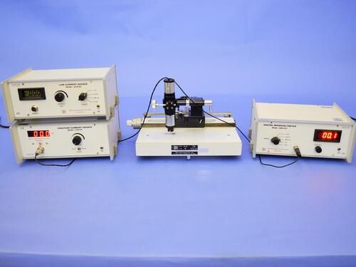
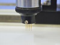
The Four Probe Method is one of the standard and most widely used method for the measurement of resistivity. In its useful form, the four probes are collinear. The error due to contact resistance, which is significant in the electrical measurement on semiconductors, is avoided by the use of two extra contacts (probes) between the current contacts. In this arrangement the contact resistance may all be high compare to the sample resistance, but as long as the resistance of the sample and contact resistance's are small compared with the effective resistance of the voltage measuring device (potentiometer, electrometer or electronic voltmeter), the measured value will remain unaffected. Because of pressure contacts, and 2 way motion, the arrangement is specially useful for quick measurement on large samples at room temperature.
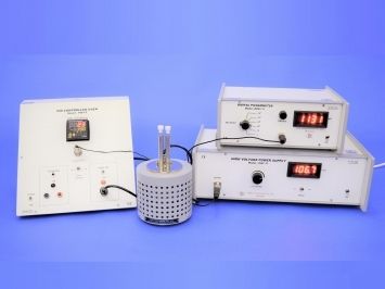
Description of Experimental Set-up
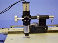
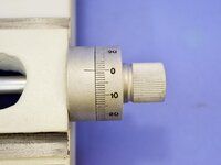
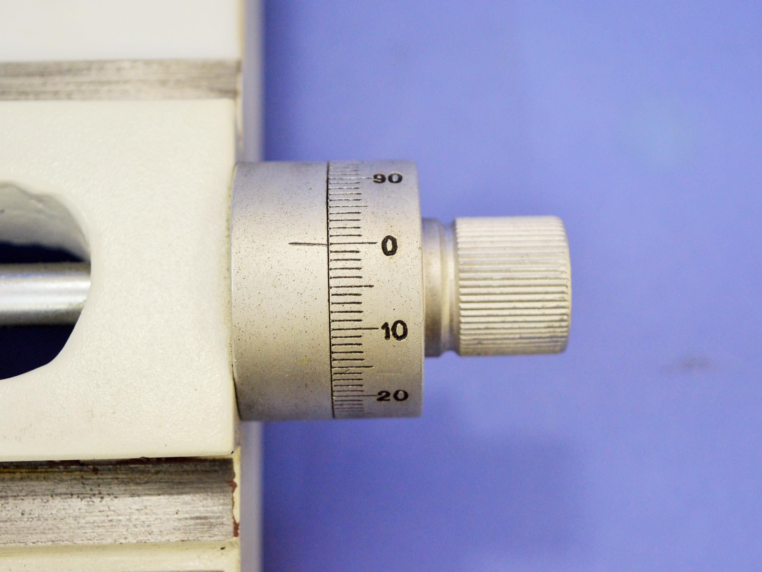
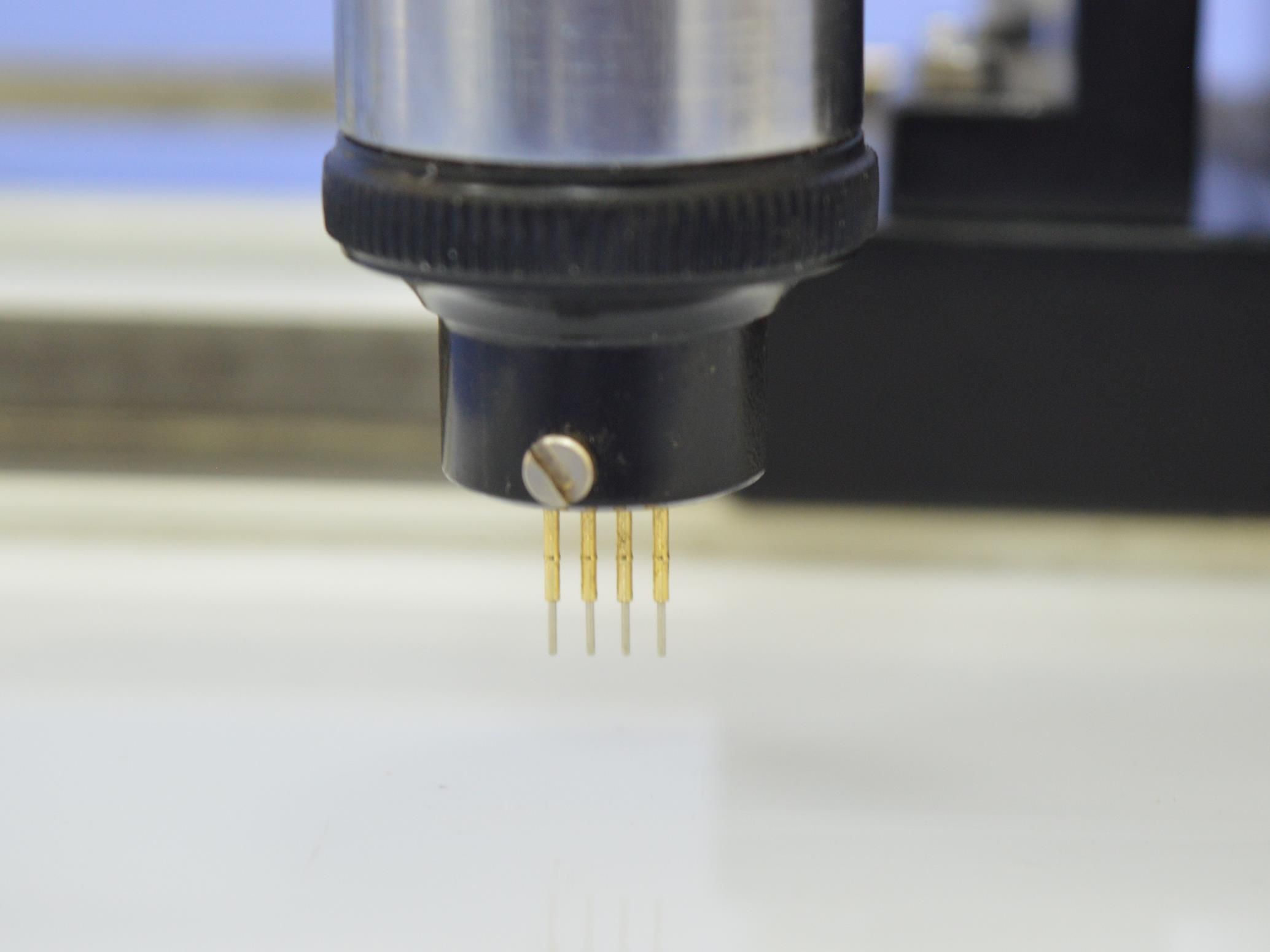
(i) Four Probe Arrangement with X-Y movement and vernier scales, FPA-FP-01
(ii) Standard Samples: Ge, Si and Aluminium, FPS-SET-3
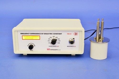
(iii) Control Unit of Four Probe Setup, DFP-RM-200N
(iv) Computer Aided Measurement Module, SES-CAMM (Optional-Extra)
Complete in all respect.
Advanced Measurement Capabilities
With its digital display and reliable electronics, the Four Probe Set Up FP-01N/ FP-01C provides precise readings of resistivity and conductivity. The system is well-suited to various laboratory experiments, ensuring researchers get accurate results for advanced material characterization.
Robust Construction for Laboratory Use
The unit's solid build and grey finish make it a practical choice for laboratory environments. Built to handle frequent use, its electronic components are designed for durability, enhancing the longevity and reliability of the instrument.
FAQ's of Four Probe Set Up FP-01N/ FP-01C:
Q: How is the Four Probe Set Up FP-01N/ FP-01C used in laboratory experiments?
A: The Four Probe Set Up is primarily utilized for measuring the electrical resistivity and conductivity of semiconductor materials. Users place the sample material on the instrument's platform, align the probes, and operate it using the digital interface to capture accurate measurements during scientific experiments.Q: What materials can be analyzed with this equipment?
A: This device is designed to analyze semiconductor samples and other electronic materials. It is suitable for experiments involving physics, electronics, and material science within laboratories.Q: When should I use the Four Probe Set Up for experimentation?
A: The Four Probe Set Up should be employed when precise measurement of electrical properties is required, particularly during research projects, academic demonstrations, or laboratory experiments involving material characterization.Q: Where is this Four Probe Set Up manufactured and supplied from?
A: This unit is manufactured, exported, and supplied in India by specialized laboratory instrument companies, ensuring adherence to quality standards for scientific research.Q: What is the process for operating the Four Probe Set Up?
A: To operate the system, set your sample onto the platform, position the four probes on the material's surface, and use the digital interface to initiate readings. The system provides direct digital display of results for easy data collection and analysis.Q: What are the benefits of using this instrument in laboratories?
A: Key benefits include high accuracy, ease of use via the digital display, durable electronic construction, and reliable data collection for semiconductor and material studies, making it an essential tool for modern laboratories.
Price:
- 50
- 100
- 200
- 250
- 500
- 1000+

Other Products in 'Physics & Material Sc. Lab Experiments' category


- Building 452, Adarsh Nagar,Roorkee - 247667, Uttarakhand, India
- Phone : 07313725920
- Mr Ravi Prakash (Director)
- Mobile :07313725920
- Send Inquiry
- Landline : 91-1332-277118/ 272852
Direct No. :+919837072750
 Send Inquiry
 Send SMS
 Call Me Free
Developed and Managed by Infocom Network Private Limited.

