 English
 Spanish
 French
 German
 Italian
 Chinese (Simplified)
 Japanese
 Korean
 Arabic
 Portuguese


Dc Position Control System, Dcp-301
Product Details:
- Weight 20 Kg Kilograms (kg)
- Application Control Laboratory Experiment
- Color Grey
- Usage Control Laboratory Experiment
- Material Electronics
- Type Control Lab Trainer
- Display Type Digital
- Click to View more
X
Dc Position Control System, Dcp-301 Price And Quantity
- 1 Set
Dc Position Control System, Dcp-301 Product Specifications
- Control Laboratory Experiment
- Grey
- Control Laboratory Experiment
- 20 Kg Kilograms (kg)
- Digital
- Control Lab Trainer
- Electronics
Dc Position Control System, Dcp-301 Trade Information
- Cash Against Delivery (CAD) Cash on Delivery (COD) Cash Advance (CA) Cash in Advance (CID) Cheque Delivery Point (DP) Telegraphic Transfer (T/T)
- 100 Set Per Month
- 1 Week
- Contact us for information regarding our sample policy
- Complete in all respect
- Asia Australia Central America North America South America Eastern Europe Western Europe Middle East Africa
- All India
- ISO 9001: 2015 CE
Product Description
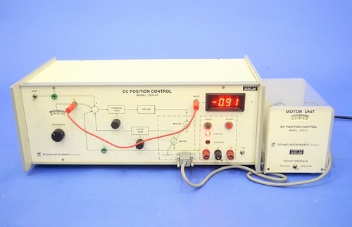
Dc Position Control System, Dcp-301
Focuses on product quality, diversity and geographical reach, we are engaged as manufacturer, supplier and exporter of DC Position Control System in Roorkee, Uttarakhand, India.
- Introduction
- One of the most common examples covered in text books and literature on linear systems is a d.c. position control system. This system is easily understood and has a second order transfer function in the standard form, for which a well developed theoretical treatment is available.
-
- This unit provides the students an opportunity to study and operate a practical electromechanical angular-position-control system. The system is built around a good quality permanent magnet armature-controlled d.c. motor, speed reduction gear-set, potentiometric error detector using special 360 revolution servo potentiometers, a tachogenerator for velocity feedback and associated electronic circuits. A PID controller with adjustable parameters is included. Unlike simulated systems, e.g. our LINEAR SYSTEM SIMULATOR, the position control system naturally consists of non-ideal parameters viz. saturation of amplifier and motor current, dead zone and backlash, nonlinearity in the motor and gears, imperfections in mechanical fabrication and somewhat uncertain order of the complete system due to filters, various time constants and load parameters. Experimental work on this system would enable the students to appreciate the difference in performance between idealized systems studied in the theory classes and the systems encountered in practice.
-
- A difficulty which is faced while working with many practical control systems is that their responses are rather slow (Note that in a simulated system the common practice is to scale-up the frequency to ensure a proper viewing on a CRO). A storage CRO or an X-Y plotter is therefore required for studying the wave forms. Both these instruments are too expensive and/or delicate, and are therefore not usually available to the undergraduate students in most institutions. The present unit has a built-in P based waveform capture/display system which stores the step response of the control system in a RAM and then displays it on a measuring CRO for further studies. This arrangement is extremely simple to operate and conforms to the accuracy needs of a class room experiment.
-
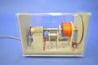
- The motor unit is housed in a separate cabinet with transparent panels for easy viewing. Interconnection with the main unit is through a standard 9-pin D-type connector. All power
- supplies and step input signal are internally provided. In addition a 3 digit DVM is available on the panel for the measurement of various.
-
- Features and Specifications
- Position control of a 12V, 1A d.c. gear motor (50 rpm)
- Provision for positive and negative tachogenerator feedback Tacho constant: 2V/1000 rpm approximately
- Calibrated dials for reference and output position: resolution 1
- Servo-potentiometers with full 360 rotation
- P based waveform capture/display card
- MATLAB interface provided
- Built-in 3 digit DVM for signal measurements
- Built-in step signal and IC regulated power supplies for electronic circuits
- Separate unit for motor in a see-through cabinet
- 220V10%, 50Hz mains operation
- Literature and patch cords included
- Essential accessories - a CRO
Tell us about your requirement

Price:
Quantity
Select Unit
- 50
- 100
- 200
- 250
- 500
- 1000+
Additional detail
Mobile number
Email

Other Products in 'Control Laboratory Experiments' category


Contact Details
- Building 452, Adarsh Nagar, Roorkee - 247667, Uttarakhand, India
- Phone : 07313725920
- Mr Ravi Prakash (Director)
- Mobile :07313725920
- Send Inquiry
- Landline : 91-1332-277118/ 272852
Direct No. :+919837072750
 Send Inquiry
 Send SMS
SES INSTRUMENTS PVT. LTD.
All Rights Reserved.(Terms of Use)
Developed and Managed by Infocom Network Private Limited.
Developed and Managed by Infocom Network Private Limited.

