 English
 Spanish
 French
 German
 Italian
 Chinese (Simplified)
 Japanese
 Korean
 Arabic
 Portuguese
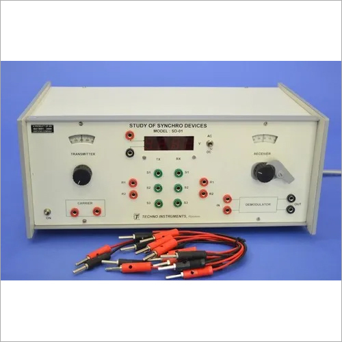

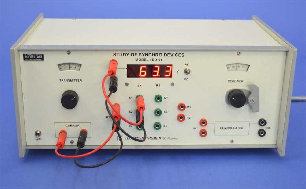
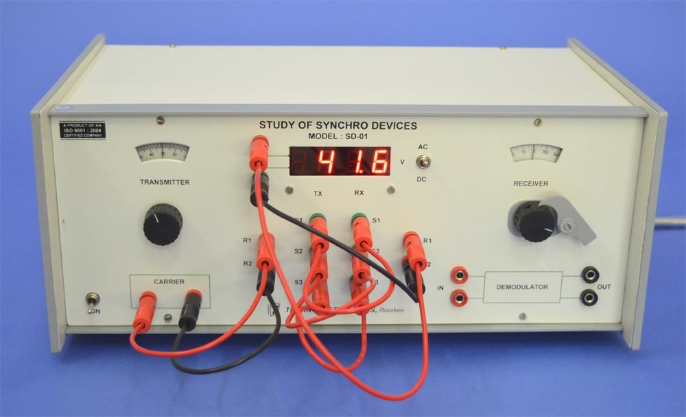
Study Of Synchro Devices, SD-01
Product Details:
- Material Electronics
- Application Control Laboratory Experiment
- Usage Control Laboratory Experiment
- Color Grey
- Weight 10 Kg Kilograms (kg)
- Type Control Lab Trainer
- Display Type Digital
- Click to View more
Study Of Synchro Devices, SD-01 Price And Quantity
- INR/Piece
- 1 Number
Study Of Synchro Devices, SD-01 Product Specifications
- Control Laboratory Experiment
- Electronics
- Control Laboratory Experiment
- Control Lab Trainer
- Digital
- 10 Kg Kilograms (kg)
- Grey
Study Of Synchro Devices, SD-01 Trade Information
- Cash on Delivery (COD) Delivery Point (DP) Telegraphic Transfer (T/T) Cash Against Delivery (CAD) Cash in Advance (CID) Cheque Cash Advance (CA)
- 100 Number Per Month
- 1 Week
- Contact us for information regarding our sample policy
- Australia North America South America Eastern Europe Western Europe Middle East Central America Asia Africa
- All India
- ISO 9001: 2015 CE
Product Description
We are instrumental in manufacturing, exporting and supplying Study Of Synchro Devices in Roorkee, Uttarakhand, India.
- Synchro transmitter-receiver pair with calibrated dials
- Locking system for receiver rotor
- Receiver use as control transformer
- Built-in balanced demodulator circuit
- Panel meter for ac/dc voltages
- All internal power from the 220V/50 Hz mains
- Only an external CRO required
EXPERIMENTS:
Basic characteristics study - stator voltages as a function of the rotor angle using the built-in ac voltmeter. This shows the space variation of the three voltages, VS1S2, VS2S3, and VS3S1, causing rotation of the resultant magnetization in the stator which is fundamental to the error detection process.
Operation and error study of the transmitter-receiver pair as a simple open loop position control at a very low torque. This is a rarely used application but is used to demonstrate the direction of the resultant magnetic field in the receiver.
Plotting the error voltage output as a function of the transmitter rotor angle with the receiver rotor locked. Observing the 180 degree phase reversal around the zero error is significant as this the basic method through which the direction of the error is detected in an ac system
Use of balanced demodulator to develop dc error signal with appropriate polarity and compare it with the ac error. This block would be needed if a mixed system were to be designed using both dc and ac components.
Other Products in 'Control Laboratory Experiments' category
- Building 452, Adarsh Nagar, Roorkee - 247667, Uttarakhand, India
- Phone : 08045475742
- Fax : 91-1332-277118
- Mr Ravi Prakash (Director)
- Mobile :08045475742
- Send Inquiry
- Landline : 91-1332-277118/ 272852
Direct No. :+919837072750

 Send Inquiry
 Send SMS
 Call Me Free
Developed and Managed by Infocom Network Private Limited.
