Study of Active Filters, AF-01
Product Details:
- Size Standard
- Style Plain
- Use Laboratory Experiment
- Surface Finish Color Coating
- Assembly No
- Material Electronics
- Shape Rectangle
- Click to View more
Study of Active Filters, AF-01 Price And Quantity
- 1 Piece
Study of Active Filters, AF-01 Product Specifications
- No
- Laboratory Experiment
- Color Coating
- Grey
- Rectangle
- Plain
- Standard
- Electronics
Study of Active Filters, AF-01 Trade Information
- Cash Against Delivery (CAD), Cash on Delivery (COD), Delivery Point (DP), Telegraphic Transfer (T/T), Cash in Advance (CID), Cheque, Cash Advance (CA)
- 100 Piece Per Month
- 1 Week
- Contact us for information regarding our sample policy
- Complete in all respect
- Asia, Australia, Central America, North America, South America, Eastern Europe, Western Europe, Middle East, Africa
- All India
- ISO 9001: 2015 CE
Product Description
Introduction
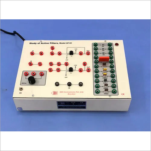
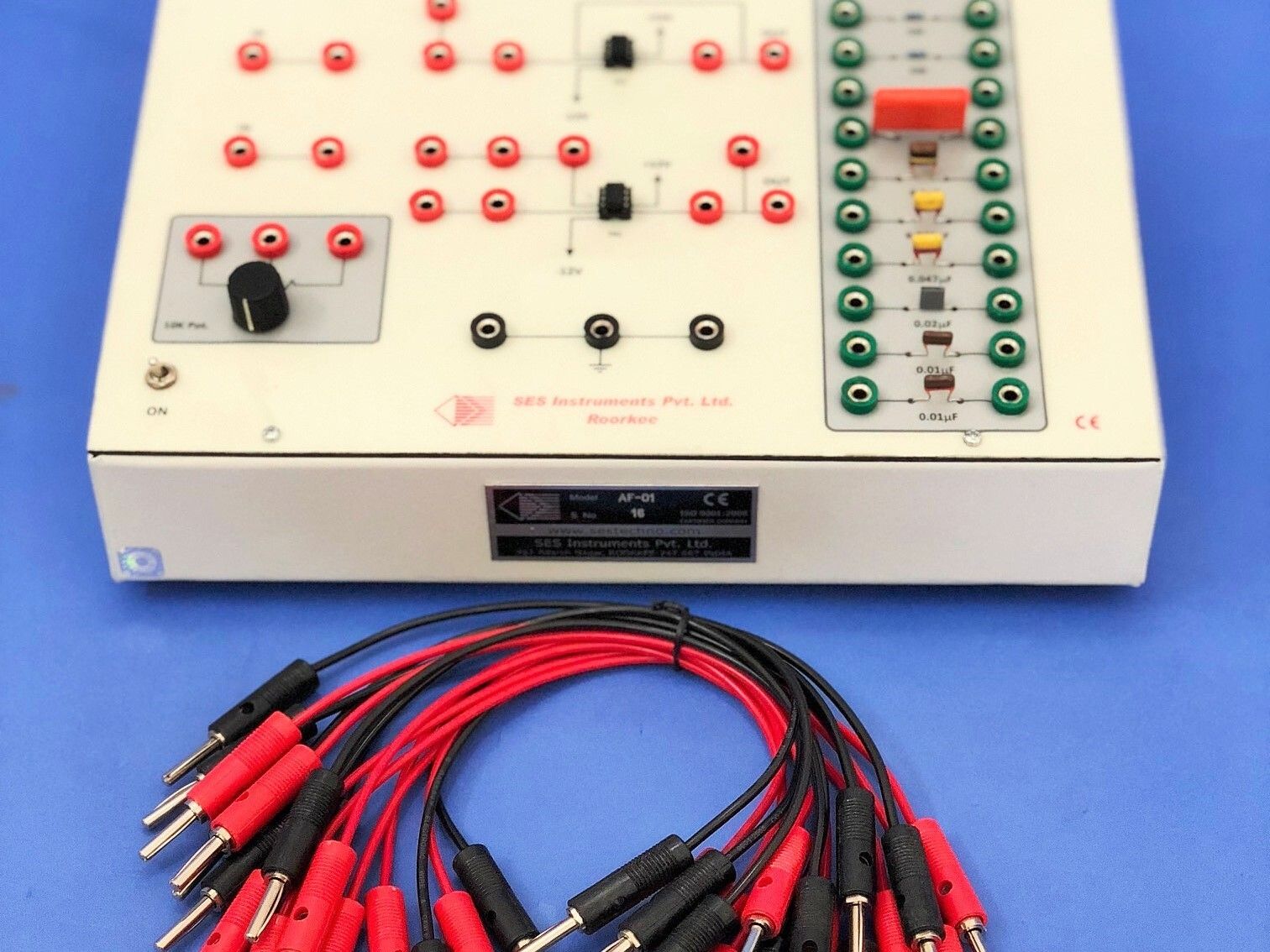
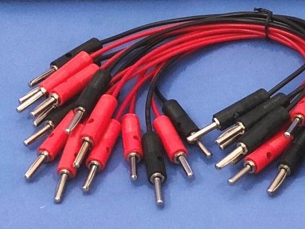
Filters are circuits which have a varied response to different frequencies and are primarily used in applications where one intends to boost or suppress some frequencies. There is naturally a very large number of filter circuits that are in use. The aim here is to suggest a few basic filters that may be constructed using the components available on the experimental board and then determine their frequency response (Bode diagram). The experimental board comprises of two operational amplifiers and some 17 passive components carefully arranged on it to be suitably connected with patchcords. A function generator and a dual traceoscilloscope would be required as an accessory for determination of the magnitude and the phase responses. The user manual supplied with the unit covers all technical details for conducting the experiments howeverit is recommended that the reader goes through a theoretical analysis of the circuits from available literature and note the significant performance characteristics of each filter that may then be verified. Although any sine wave source may be used for the experiment, we recommend a DDS dual channel function generator Type JDS 6600 which greatly simplifies the measurements.
Designed for Effective Laboratory Learning
The AF-01 Active Filters study kit is tailor-made for laboratory experimentation, allowing users to gain direct hands-on experience with various filter circuits. With clear labeling and a straightforward structure, it simplifies the comprehension of complex electronic concepts, making it ideal for both teaching and self-study environments in academic institutions.
Durable and User-Friendly Construction
Engineered using sturdy electronic materials and finished with color coating, the AF-01 assures long-lasting performance. Its rectangular shape and plain style promote hassle-free placement and usability in standard lab settings, while its 4 kg weight ensures stability during experiments without requiring assembly.
Versatile Applications in Electronics Education
Specially designed for laboratory experiments, the AF-01 enables in-depth investigation of active filter operations. Suitable for institutions seeking to train students practically, this device aids in demonstrating the real-world functionality of filters, bridging the gap between theoretical knowledge and practical application.
FAQ's of Study of Active Filters, AF-01:
Q: How is the Study of Active Filters, AF-01, typically used in laboratory experiments?
A: The AF-01 is used to conduct experiments on different types of active filters, such as low-pass, high-pass, band-pass, and band-stop filters. Students and instructors apply various input signals and observe the output characteristics, helping them understand how active filters function in practical circuits.Q: What benefits does the AF-01 offer compared to simple passive filter kits?
A: The AF-01 provides a hands-on approach to exploring active filter circuits, which involve amplifying components. Unlike passive filter kits, it allows users to experiment with circuits that offer gain and better performance, leading to a deeper comprehension of advanced electronic concepts.Q: When should the AF-01 be introduced in an educational curriculum?
A: The AF-01 is recommended once foundational electronic theories and passive filter concepts have been covered. Introducing this kit during the intermediate stages of electronics courses enables students to progress naturally from basic to advanced practical filter applications.Q: Where can the AF-01 be purchased and who supplies it?
A: The AF-01 is manufactured, exported, and supplied by reputable companies in India. Interested institutions or laboratories can contact local exporters, manufacturers, or authorized suppliers to purchase the kit, ensuring genuine product quality and support.Q: What is the process for conducting experiments with the AF-01 Active Filters kit?
A: Users connect the device as per the provided instructions and circuits, select the desired type of filter, and apply input signals. Oscilloscopes or multimeters are used to measure the output and analyze filter behavior, supporting comprehensive experimental learning.Q: How does the surface finish and material contribute to the AF-01's reliability and usability?
A: The color-coated finish and durable electronic materials ensure resistance to wear and environmental factors, promoting longevity in repeated use. Its easy-to-clean exterior and robust construction make it reliable for continuous laboratory application.Q: What are the key applications and benefits of using the AF-01 in a laboratory setting?
A: The AF-01 is primarily used for educational laboratory experiments, providing practical exposure to active filter design and functionality. It enhances theoretical learning, fosters critical thinking, and prepares students for advanced studies or careers in electronics.
Price:
- 50
- 100
- 200
- 250
- 500
- 1000+
 English
 Spanish
 French
 German
 Italian
 Chinese (Simplified)
 Japanese
 Korean
 Arabic
 Portuguese






 Send Inquiry
 Send SMS
 Call Me Free
