 English
 Spanish
 French
 German
 Italian
 Chinese (Simplified)
 Japanese
 Korean
 Arabic
 Portuguese


Magnetoresistance Setup (Research Model), MRX-RMN/ MRX-RMC
Product Details:
- Usage Laboratory use
- Application Laboratory use
- Material Electronics
- Weight 170 Kg
- Color Grey
- Display Type Digital
- Click to View more
Magnetoresistance Setup (Research Model), MRX-RMN/ MRX-RMC Price And Quantity
- 1 Set
Magnetoresistance Setup (Research Model), MRX-RMN/ MRX-RMC Product Specifications
- Grey
- 170 Kg
- Electronics
- Laboratory use
- Laboratory use
- Digital
Magnetoresistance Setup (Research Model), MRX-RMN/ MRX-RMC Trade Information
- Cash Against Delivery (CAD), Cash on Delivery (COD), Cash Advance (CA), Cash in Advance (CID), Cheque, Delivery Point (DP), Telegraphic Transfer (T/T)
- 100 Set Per Month
- 1 Week
- Contact us for information regarding our sample policy
- Complete in all respect
- Asia, Australia, Central America, North America, South America, Eastern Europe, Western Europe, Middle East, Africa
- All India
- ISO 9001: 2015 CE
Product Description
Magnetoresistance Setup (Research Model), MRX-RMN/ MRX-RMC
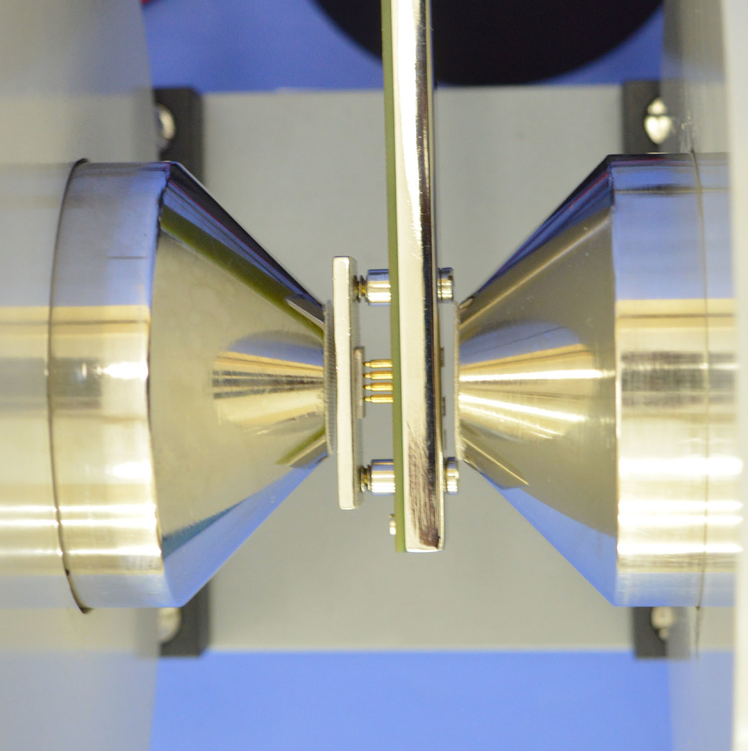
It is noticed that the resistance of the sample changes when the magnetic field is turned on. The phenomenon, called magnetoresistance, is due to the fact that the drift velocity of all carriers is not same. With the magnetic fieldon; the Hall voltage V=E t=| x | compensates exactly y v H the Lorentz force for carriers with the average velocity; slower carriers will be over compensated and faster one under compensated, resulting in trajectories that are not along the applied field. This results in an effective decrease of the mean free path and hence an increase in resistivity. Here the above referred symbols are defines as: v = drift velocity; E = applied electric field; t = thickness of the crystal; H = Magnetic field.
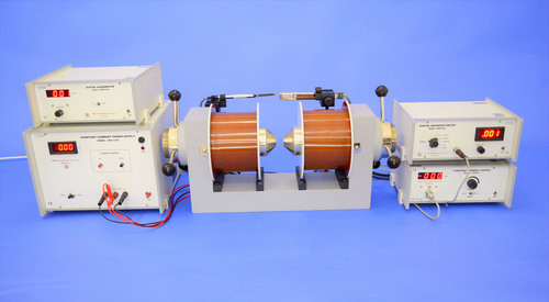
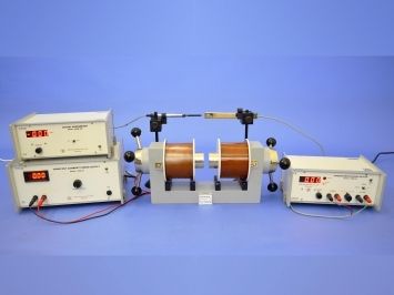
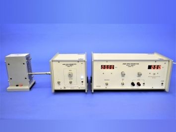
Experimentental Set-up for Magnetoresistance The set-up consists of the following:
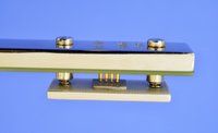
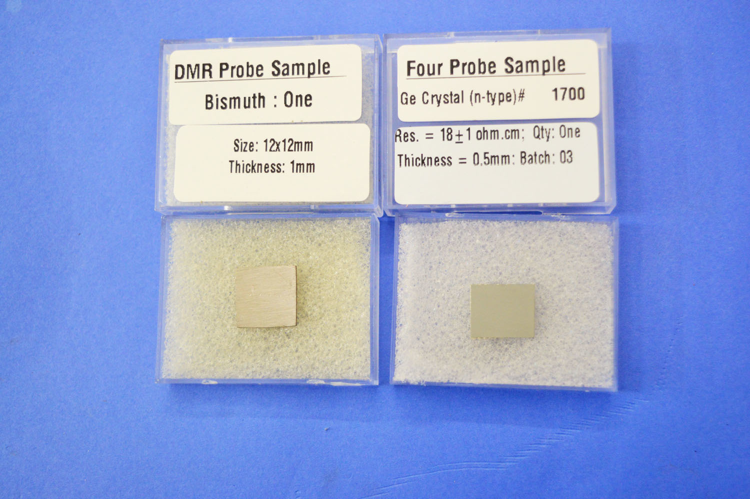
- (i) Four Probe Arrangement suitable for MRX-Research, FPA-MRX-RM
- (ii) Sample: Ge Crystal (n-type), Sample: Bismuth, MRB-SBi
- (iii) Hall Probe Multipurpose Stand, HPS
- (iv) Control Unit of Four Probe Setup, DFP-RM-200N
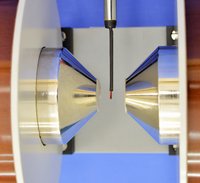
- (v) Electromagnet, EMU-75
- (vi) Constant Current Power Supply, DPS-175-C2
- (vii) Digital Gaussmeter, DGM-202-C1
- (viii) Computer Aided Measurement Module, SES-CAMM (optional extra)
- Complete in all respect
Advanced Magnetoresistance Analysis
The MRX-RMN/ MRX-RMC Magnetoresistance Setup is engineered to facilitate in-depth study of magnetoresistance in diverse materials. Its digital interface enhances measurement precision and user accessibility. Designed for rigorous laboratory use, this instrument offers exceptional durability and consistency in experimental results, making it a preferred choice for both academic and industrial research applications.
Reliable Performance for Laboratories
Constructed from top-grade electronics, the setup ensures stable operation and robust performance. Its substantial weight and sturdy design provide stability during experiments, while its manufacturer's commitment to quality guarantees long-term reliability. This equipment is suitable for frequent laboratory use thanks to its ease of operation and minimal maintenance requirements.
FAQ's of Magnetoresistance Setup (Research Model), MRX-RMN/ MRX-RMC:
Q: How does the Magnetoresistance Setup MRX-RMN/ MRX-RMC function in laboratory research?
A: The setup operates by applying controlled magnetic fields to test samples and accurately measuring changes in electrical resistance. Its digital display allows researchers to easily monitor and record data in real time, streamlining the analysis process for complex experiments.Q: What benefits does using a digital display offer compared to analog models?
A: A digital display enhances precision and user experience by providing clear, stable readings. It minimizes interpretation errors, ensures easier tracking of experimental data, and simplifies integration with data logging systems commonly used in laboratory environments.Q: Where is the Magnetoresistance Setup MRX-RMN/ MRX-RMC primarily used?
A: This instrument is primarily utilized in laboratory settings within research institutions, universities, and industry labs focused on material science and condensed matter physics. It is exported and supplied internationally from India.Q: When should researchers use the Magnetoresistance Setup for their experiments?
A: Researchers should employ this setup when precise measurement of magnetoresistance properties is necessary, particularly in studies involving new materials or electronic characterization. It is recommended during advanced phases of laboratory investigations where accuracy is critical.Q: What is the standard process for operating this magnetoresistance setup?
A: Operation involves securing the test sample in the unit, configuring magnetic fields and electrical parameters via the digital interface, and monitoring the resistance measurements as the magnetic field varies. The process is designed to be user-friendly for efficient experimental workflow.Q: How does this setup benefit laboratory research compared to other alternatives?
A: The MRX-RMN/ MRX-RMC provides reliable, repeatable results due to its robust construction and advanced digital controls. Its stability and accuracy help accelerate research, reduce measurement errors, and advance material studies for innovative applications.
Price:
- 50
- 100
- 200
- 250
- 500
- 1000+

Other Products in 'Physics & Material Sc. Lab Experiments' category


- Building 452, Adarsh Nagar,Roorkee - 247667, Uttarakhand, India
- Phone : 07313725920
- Mr Ravi Prakash (Director)
- Mobile :07313725920
- Send Inquiry
- Landline : 91-1332-277118/ 272852
Direct No. :09837072750
 Send Inquiry
 Send SMS
 Call Me Free
Developed and Managed by Infocom Network Private Limited.

