 English
 Spanish
 French
 German
 Italian
 Chinese (Simplified)
 Japanese
 Korean
 Arabic
 Portuguese


Four Probe Setup, DFP-LHN/ DFP-LHC
Product Details:
- Usage Laboratory use
- Material Electronics
- Application Laboratory use
- Weight 40 Kg
- Color Grey
- Display Type Digital
- Click to View more
Four Probe Setup, DFP-LHN/ DFP-LHC Price And Quantity
- 1 Set
Four Probe Setup, DFP-LHN/ DFP-LHC Product Specifications
- Laboratory use
- 40 Kg
- Grey
- Laboratory use
- Digital
- Electronics
Four Probe Setup, DFP-LHN/ DFP-LHC Trade Information
- Cash Against Delivery (CAD), Cash on Delivery (COD), Cash Advance (CA), Cash in Advance (CID), Cheque, Delivery Point (DP), Telegraphic Transfer (T/T)
- 100 Set Per Month
- 1 Week
- Contact us for information regarding our sample policy
- Complete in all respect
- Australia, North America, South America, Eastern Europe, Western Europe, Middle East, Central America, Asia, Africa
- All India
- ISO 9001: 2015 CE
Product Description
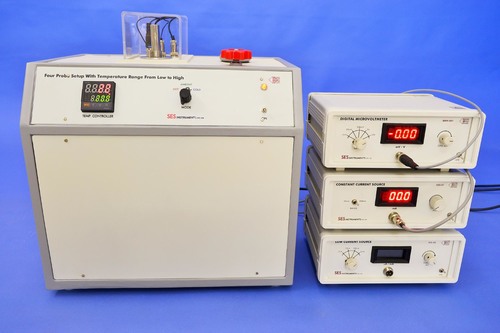
Four Probe Setup,DFP-LHN/ DFP-LHC
The Four Probe Method is one of the standard and most widely used method for the measurement of resistivity. In its useful form, the four probes are collinear. The error due to contact resistance, which is significant in the electrical measurement on semiconductors, is avoided by the use of two extra contacts (probes) between the current contacts. In this arrangement the contact resistance may all be high compare to the sample resistance, but as long as the resistance of the sample and contact resistance's are small compared with the effective resistance of the voltage measuring device (potentiometer, electrometer or electronic voltmeter), the measured value will remain unaffected. Because of pressure contacts, the arrangement is also specially useful for quick measurement on different samples or sampling different parts of the sample.
Description of Experimental Set-up:
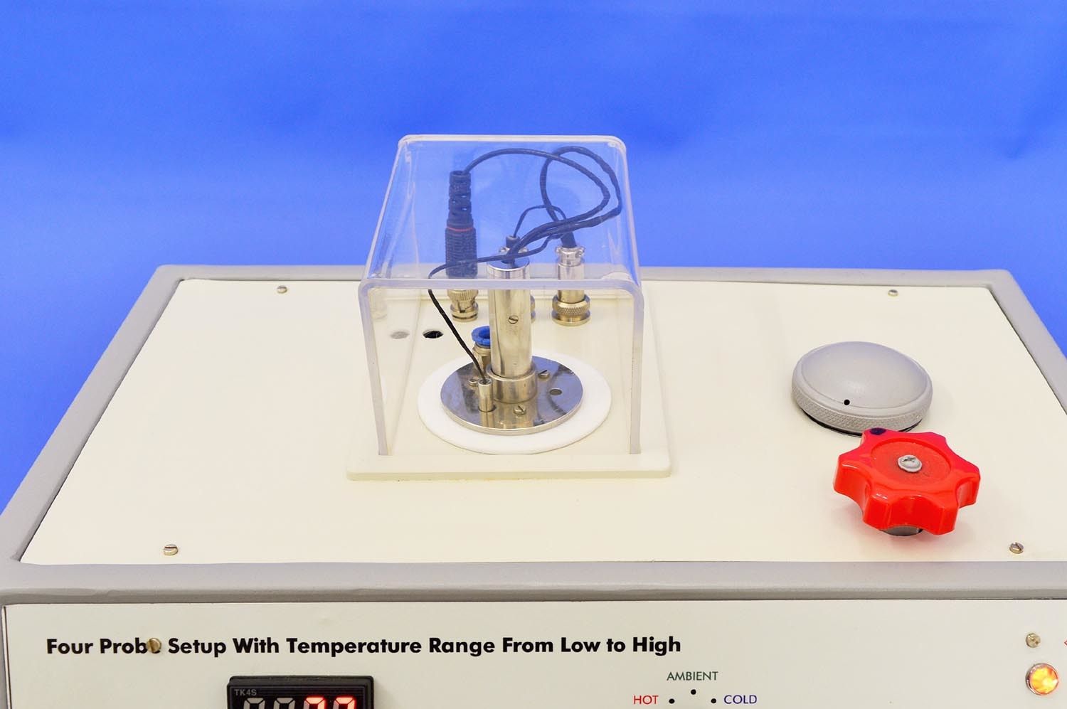
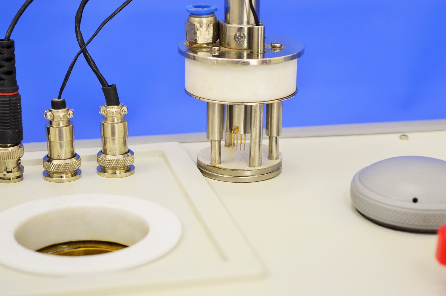
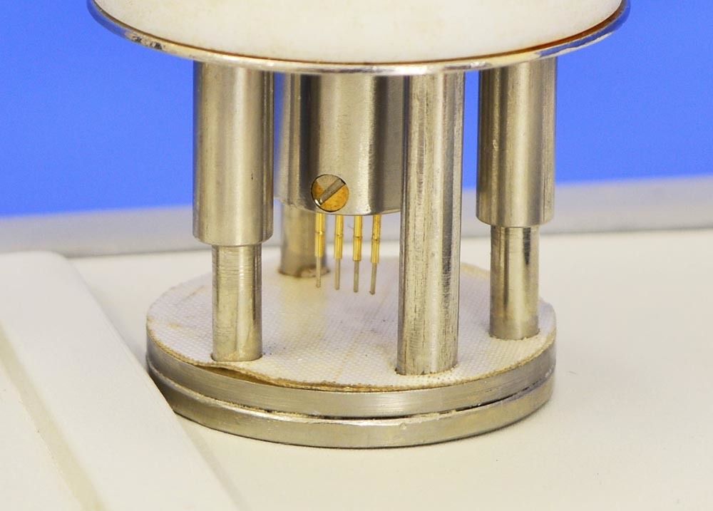
1. Probes Arrangement
It has four individually spring loaded probes. The probes are collinear and equally spaced. The probes are mounted in a teflon bush, which ensure a good electrical insulation between the probes. A teflon spacer near the tips is also provided to keep the probes at equal distance. The probe arrangement is mounted in a suitable stand, which also holds the sample plate and Thermocouple sensor. This stand also serves as the lid of PID Controlled Oven. Proper leads are provided for the current and voltage measurements.
2. PID Controlled Oven cum Cryostate
In this unit heating of sample zone is done through heating coil and cooling through controlled flow of liquid nitrogen. The necessary components such as the cryostate, the flow system etc. are included.
Temperature range is from -170C to 200C. The unit is a high quality PID controller wherein the temperatures can be set and controlled easily. The P, I and D parameters are factory set for immediate use however the user may adjust these for specific applications as well as auto-tune the oven whenever required. The steps for these are given in the user manual.
Specifications of the Temperature Controller
The controller is designed around Autonics Temperature Controller Model TK4S. Although this is a very versatile piece of equipment, below is a summary of the specifications that are relevant to the present application.
Temperature Range: -170C to 200C
Oven: Specially designed for Four Probe Set-Up
Display Accuracy: +-0.3C
Sensor: Thermocouple (Chromel-Alumel)
Setting Type: Front push buttons
Display: 7 segment LED, two rows
Control Method: PID, PIDF, PIDS
Values: Process Value, PV and Set Value, SV
Temperature control range: Ambient to 200C
Power: 150W
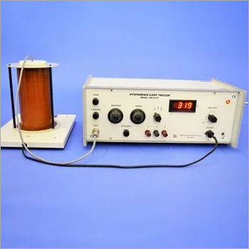
3. Control Unit of Four Probe Setup
The unit comprises of two sections a totally isolated constant current source, and a grounded voltage measurement system. Features of these two sections are described below in some detail.
(A) Constant Current Source
It is an IC regulated current generator that is galvanically isolated from the rest of the circuit which is a basic requirement of four probe method. The isolation is achieved by using an optically coupled amplifier and associated circuits. This circuit sends a constant Current. To the changing resistance of the sample due to change in temp..
A judicious choice of the current setting as detailed in the user manual is necessary depending on the resistance value that is measured. Brief technical details of the current section are as under:
Current Range: 2 A, 20 A, 200 A, 2mA, 20mA and 200mA with over ranging
Open Circuit Voltage: 15V in the lower four ranges and 9V in the upper two
Accuracy : 0.25% of the reading 1digit
4-line LCD display with indication when current needs decreasing
(b) Digital Voltmeter Section
The voltmeter is used to read the voltage developed between the middle pins of the four probe arrangement. A primary requirement is to have very high input resistance so that the measurement is not disturbed in case of high resistance samples. The input range of the voltmeter is thus limited by avoiding the use of any potential divider. Brief technical details are as under:
Voltage Range: 2mV, 20 mV, 200 mV, 2V with over ranging
Manual adjustment of Offset Voltage whenever current/voltage range is changed
Accuracy : 0.25% of the reading 1 digit
4-line LCD display with over voltage indication
In addition to the above, the Four Probe Setup as well as the PID Oven cum Cryostate Unit may be connected to a computer for data logging purposes. Necessary hardware and software are included in the system.
The setup is complete in itself
Precise Laboratory Measurements
The Four Probe Setup DFP-LHN/DFP-LHC offers reliable data acquisition for scientists and students, making it essential for conductivity and resistivity measurements in electronic laboratories. Its digital display ensures clarity while handling complex experiments.
Built for Durability and Stability
Constructed with quality electronic materials and weighing 40 kg, this setup maintains stability during extended laboratory use. Its robust design reduces measurement errors, ensuring consistent performance in academic and research settings.
Manufactured and Supplied in India
Produced in India by reputed manufacturers and suppliers, the Four Probe Setup adheres to international standards. Its availability through exporters ensures it reaches laboratories worldwide, supporting scientific advancement and research.
FAQ's of Four Probe Setup, DFP-LHN/ DFP-LHC:
Q: How does the Four Probe Setup DFP-LHN/DFP-LHC function in laboratory measurements?
A: This instrument utilizes four probes to accurately determine the resistivity and conductivity of various materials by applying a current and measuring the resulting voltage, providing precise electronic data through its digital display.Q: What are the main components and features of the Four Probe Setup?
A: The setup consists of four precision probes, a robust electronic base, a digital readout, and a user-friendly interface. Its grey color, digital display type, and substantial 40 kg weight contribute to stability and ease of data interpretation.Q: When should laboratories use the Four Probe Setup for experiments?
A: Laboratories should employ this setup when conducting research or educational experiments requiring accurate measurement of material resistivity and conductivity, particularly in solid-state physics and electronic testing applications.Q: Where is the Four Probe Setup manufactured and how can it be obtained?
A: This equipment is manufactured in India and is available through exporters, manufacturers, and suppliers. Laboratories worldwide can acquire it by contacting authorized distributors or visiting the manufacturer's official online platform.Q: What is the process for using the Four Probe Setup in conductivity analysis?
A: Users position the material sample under the probes, activate the instrument to introduce current, and then observe the digital display for voltage readings. These readings are used to calculate the material's conductivity and resistivity.Q: What are the benefits of using a digital Four Probe Setup in laboratory settings?
A: The digital display enables precise data acquisition and reduces human error, while the sturdy build ensures consistent measurement results. Its reliability improves experimental outcomes and aids in both instructional and research environments.Q: How does the Four Probe Setup enhance laboratory research and education?
A: By providing accurate, dependable measurements, it supports the validation of theoretical models and enhances practical understanding of electronic properties, making it a valuable tool for both teaching and advanced scientific research.
Price:
- 50
- 100
- 200
- 250
- 500
- 1000+

Other Products in 'Physics & Material Sc. Lab Experiments' category


- Building 452, Adarsh Nagar,Roorkee - 247667, Uttarakhand, India
- Phone : 07313725920
- Mr Ravi Prakash (Director)
- Mobile :07313725920
- Send Inquiry
- Landline : 91-1332-277118/ 272852
Direct No. :+919837072750
 Send Inquiry
 Send SMS
 Call Me Free
Developed and Managed by Infocom Network Private Limited.

