 English
 Spanish
 French
 German
 Italian
 Chinese (Simplified)
 Japanese
 Korean
 Arabic
 Portuguese

Magnetoresistance in Bismuth, MRB-11/ MRB-11C
Product Details:
Magnetoresistance in Bismuth, MRB-11/ MRB-11C Price And Quantity
- INR/Set
- 1 Set
Magnetoresistance in Bismuth, MRB-11/ MRB-11C Trade Information
- Cash on Delivery (COD) Telegraphic Transfer (T/T) Delivery Point (DP) Cash Against Delivery (CAD) Cash in Advance (CID) Cheque Cash Advance (CA)
- 100 Set Per Month
- 1 Week
- Contact us for information regarding our sample policy
- Australia North America South America Eastern Europe Western Europe Middle East Africa Central America Asia
- All India
- ISO 9001: 2015 CE
Product Description
It is noticed that the resistance of the sample changes when the magnetic field is turned on. The phenomenon, called magnetoresistance, is due to the fact that the drift velocity of all the carriers is not same. With the magnetic field on; the Hall voltage V = Eyt = v -H compensates exactly the Lorentz force
for carriers with the average velocity; slower carriers will be over compensated and faster one undercompensated, resulting in trajectories that are not along the applied field. This results in an effective decrease of the mean free path and hence an increase in resistivity.
Here the above referred symbols are defined as: v = drift velocity; E = applied electric field; t = thickness of the crystal; H = Magnetic field
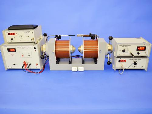
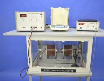
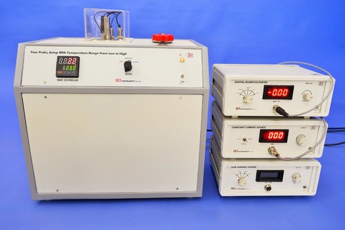
EXPERIMENTENTAL SET-UP FOR MAGNETORESISTANCE
The set-up consists of the following:
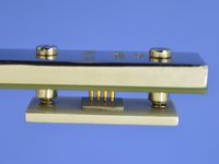
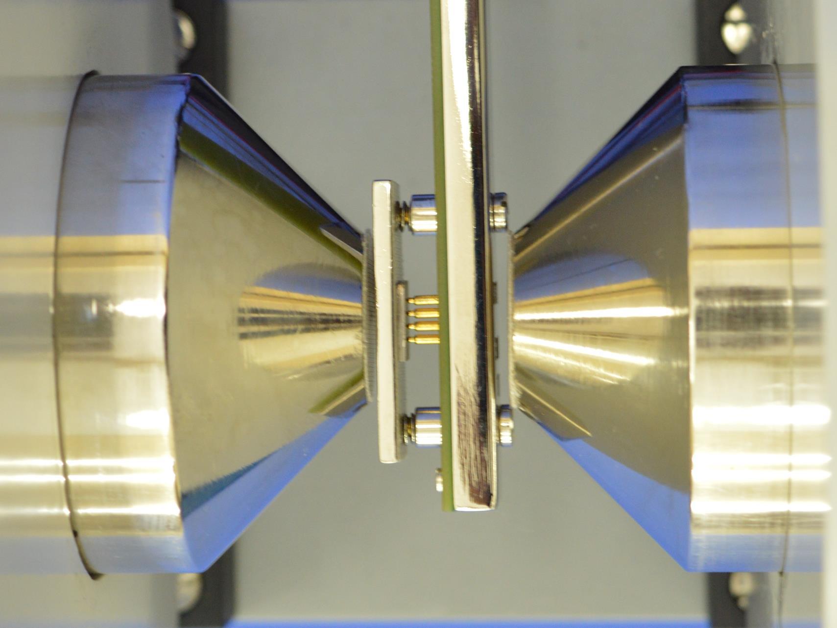
1. Probes Arrangement
It consists of 4 collinear, equally spaced (2mm) and individually spring loaded probes mounted on a PCB strip. Two outer probes for supplying the constant current to the sample and two inner probes for
measuring the voltage developed across these probes. This eliminates the error due to contact resistance which is particularly serious in semiconductors. A platform is also provided for placing the sample and mounting the Four Probes on it.
2. Control Unit of Four Probe Setup
The unit comprises of two sections a totally isolated constant current source, and a grounded voltage measurement system. Features of these two sections are described below in some detail.
(A) Constant Current Source
It is an IC regulated current generator that is galvanically isolated from the rest of the circuit which is a basic requirement of four probe method. The isolation is achieved by using an optically coupled amplifier and associated circuits. This circuit sends a constant Current. To the changing resistance of the sample due to change in temp..
A judicious choice of the current setting as detailed in the user manual is necessary depending on the resistance value that is measured. Brief technical details of the current section are as under:
Current Range: 2 A, 20 A, 200 A, 2mA, 20mA and 200mA with over ranging
Open Circuit Voltage: 15V in the lower four ranges and 9V in the upper two
Accuracy : 0.25% of the reading 1digit
4-line LCD display with indication when current needs decreasing
(b) Digital Voltmeter Section
The voltmeter is used to read the voltage developed between the middle pins of the four probe arrangement. A primary requirement is to have very high input resistance so that the measurement is not disturbed in case of high resistance samples. The input range of the voltmeter is thus limited by avoiding the use of any potential divider. Brief technical details are as under:
Voltage Range: 2mV, 20 mV, 200 mV, 2V with over ranging
Manual adjustment of Offset Voltage whenever current/voltage range is changed
Accuracy : 0.25% of the reading 1 digit
4-line LCD display with over voltage indication
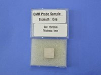
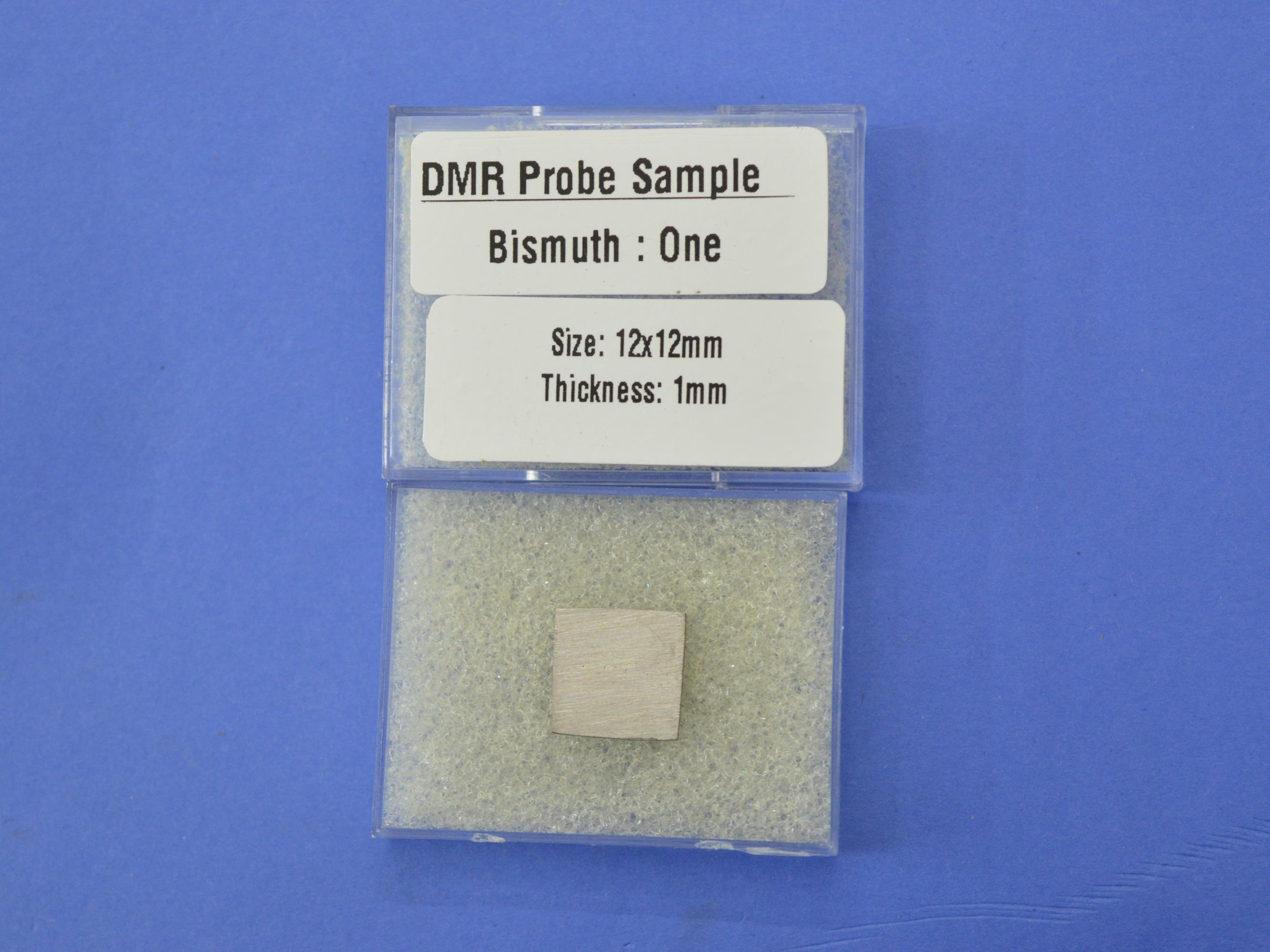
3. Standard Sample
Bismuth (dimensions: 10 x 10 x 1.2mm)
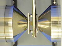
4. Electromagnet, EMU-75T (Refer datasheet for specifications)
5. Constant Current Power Supply, DPS-175-C2 (Refer datasheet for specifications)
6. Digital Gaussmeter, DGM-202-C1 (Refer datasheet for specifications)
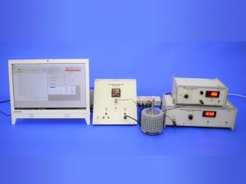
7. SES-CAMM
This is SES computer aided measurement module, which act as an interface between computer and different subunits of this experiment.
In addition to the above, this Magnetoresistance Setup may be connected to a computer for data logging purposes. Necessary hardware and software are included in the system.
The setup is complete in itself
Other Products in 'Physics & Material Sc. Lab Experiments' category

- Building 452, Adarsh Nagar, Roorkee - 247667, Uttarakhand, India
- Phone : 08045475742
- Fax : 91-1332-277118
- Mr Ravi Prakash (Director)
- Mobile :08045475742
- Send Inquiry
- Landline : 91-1332-277118/ 272852
Direct No. :+919837072750

 Send Inquiry
 Send SMS
 Call Me Free
Developed and Managed by Infocom Network Private Limited.
